Sunday, 5 May 2013

The Instrument Landing System


The Instrument Landing System

A. GENERAL DESCRIPTION
Instrument landing system (ILS) facilities are a highly accurate and dependable means of navigating to the runway in IFR conditions. When using the ILS, the pilot determines aircraft position primarily by reference to instruments. The ILS consists of:

  1. the localizer transmitter;
  2. the glide path transmitter;
  3. the outer marker (can be replaced by an NDB or other fix);
  4. the approach lighting system.
ILS is classified by category in accordance with the capabilities of the ground equipment. Category I ILS provides guidance information down to a decision height (DH) of not less than 200 ft. Improved equipment (airborne and ground) provide for Category II ILS approaches.
A DH of not less than 100 ft. on the radar altimeter is authorized for Category II ILS approaches.
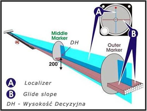
The ILS provides the lateral and vertical guidance necessary to fly a precision approach, where glide slope information is provided. A precision approach is an approved descent procedure using a navigation facility aligned with a runway where glide slope information is given. When all components of the ILS system are available, including the approved approach procedure, the pilot may execute a precision approach.
B. LOCALIZER
1. GROUND EQUIPMENT: The primary component of the ILS is the localizer, which provides lateral guidance. The localizer is a VHF radio transmitter and antenna system using the same general range as VOR transmitters (between 108.10 MHz and 111.95 MHz). Localizer frequencies, however, are only on odd-tenths, with 50 kHz spacing between each frequency. The transmitter and antenna are on the centerline at the opposite end of the runway from the approach threshold.
The localizer back course is used on some, but not all ILS systems. Where the back course is approved for landing purposes, it is generally provided with a 75 MHz back marker facility or NDB located 3 to 5 NM from touchdown. The course is checked periodically to ensure that it is positioned within specified tolerances.
2. SIGNAL TRANSMISSION: The signal transmitted by the localizer consists of two vertical fan-shaped patterns that overlap, at the center (see ILS Localizer Signal Pattern figure, below). They are aligned with the extended centerline of the runway. The right side of this pattern, as seen by an approaching aircraft, is modulated at 150 Hz and is called the "blue" area. The left side of the pattern is modulated at 90 Hz and is called the "yellow" area. The overlap between the two areas provides the on-track signal.
The width of the navigational beam may be varied from approximately 3º to 6º, with 5º  being normal. It is adjusted to provide a track signal approximately 700 ft wide at the runway threshold. The width of the beam increases so that at 10 NM from the transmitter, the beam is approximately one mile wide.
2-81.jpg (11343 bytes)
The localizer is identified by an audio signal superimposed on the navigational signal. The audio signal is a two-letter identification preceded by the letter "I", e.g., " I-OW ".
The reception range of the localizer is at least 18 NM within 10º degrees of the on-track signal. In the area from l0º to 35º    of the on-track signal, the reception range is at least 10 NM. This is because the primary strength of the signal is aligned with the runway centerline.
3. LOCALIZER RECEIVER: The localizer signal is received in the aircraft by a localizer receiver. The localizer receiver is combined with the VOR receiver in a single unit. The two receivers share some electronic circuits and also the same frequency selector, volume control, and ON-OFF control.
The localizer signal activates the vertical needle called the track bar (TB). Assuming a final approach track aligned north and south (see ILS Localizer Signal Pattern figure, above), an aircraft east of the extended centerline of the runway (position 1) is in the area modulated at 150 Hz. The TB is deflected to the left. Conversely, if the aircraft is in the area west of the runway centerline, the 90 Hz signal causes the TB to deflect to the right (position 2). In the overlap area, both signals apply a force to the needle, causing a partial deflection in the direction of the strongest signal. Thus, if an aircraft is approximately on the approach track bur slightly to the right, the TB is deflected slightly to the left. This indicates that a correction to the left is necessary to place the aircraft in precise alignment.
At the point where the 90 Hz and 150 Hz signals are of equal intensity, the TB is centered, indicating that the aircraft is located precisely on the approach track(position 3).
When the TB is used in conjunction with the VOR, full scale needle deflection occurs 10º either side of the track shown on the track selector. When this same needle is used as an ILS localizer indicator, full-scale needle deflection occurs at approximately 2.5º from the center of the localizer beam.
Thus the sensitivity of the TB is approximately four times greater when used as a localizer indicator as opposed to VOR navigation.
In the localizer function, the TB does not depend on a correct track selector setting in Most cases; however, the pilot should set the track selector for the approach track as a reminder of the final approach.
When an OFF flag appears in front of the vertical needle, it indicates that the signal is too weak, and, therefore, the needle indications arc unreliable. A momentary OFF flag, or brief TB needle deflections, or both, may occur when obstructions or other aircraft pass between the transmitting antenna and the receiving aircraft.
C. GLIDE SLOPE EQUIPMENT
1. TRANSMITTER: The glide slope provides vertical guidance to the pilot during the approach. The ILS glide slope is produced by a ground-based UHF radio transmitter and antenna system, operating at a range of 329.30 MHz to 335.00 MHz, with a 50 kHz spacing between each channel. The transmitter is located 750 to 1,250 feet (ft) down the runway from the threshold, offset 400 to 600 ft from the runway centerline. Monitored to a tolerance of ± 1/2 degree, the UHF glide path is "paired" with (and usually automatically tuned by selecting) a corresponding VHF localizer frequency.
Like the localizer, the glide slope signal consists of two overlapping beams modulated at 90 Hz and 150 Hz (see Glide Slope Signal Pattern figure, below). Unlike the localizer, however, these signals are aligned above each other and are radiated primarily along the approach track. The thickness of the overlap area is 1.4º or .7º above and .7º below the optimum glide slope.
2-83.gif (6971 bytes)
This glide slope signal may be adjusted between 2º and 4.5º above a horizontal plane. A typical. adjustment is 2.5º to 3º, depending upon such factors as obstructions along the approach path and the runway slope.
False signals may be generated along the glide slope in multiples of the glide path angle, the first being approximately 6º degrees above horizontal. This false signal will be a reciprocal signal (i.e. the fly up and fly down commands will be reversed). The false signal at 9º will be oriented in the same manner as the true glide slope. There are no false signals below the actual slope. An aircraft flying according to the published approach procedure on a front course ILS should not encounter these false signals.
2. SIGNAL RECEIVER: The glide slope signal is received by a UHF receiver in the aircraft. In modern avionics installations, the controls for this radio are integrated with the VOR controls so that the proper glide slope frequency is tuned automatically when the localizer frequency is selected.
The glide slope signal activates the glide slope needle, located in conjunction with the TB (see Glide Slope Signal Pattern figure, above). There is a separate OFF flag in the navigation indicator for the glide slope needle. This flag appears when the glide slope signal is too weak. As happens with the localizer, the glide slope needle shows full deflection until the aircraft reaches the point of signal overlap. At this time, the needle shows a partial deflection in the direction of the strongest signal. When both signals are equal, the needle centers horizontally, indicating that the aircraft is precisely on the glide path.
The pilot may determine precise location with respect to the approach path by referring to a single instrument because the navigation indicator provides both vertical and lateral guidance. In the Glide Slope Signal Pattern figure, above,   position 1, shows both needles centered, indicating that the aircraft is located in the center of the approach path. The indication at position 2 tells the pilot to fly down and left to correct the approach path. Position 3 shows the requirements to fly up and right to reach the proper path. With 1.4º of beam overlap, the area is approximately 1,500 ft thick at 10 nautical miles (NM), 150 ft at l NM, and less than one foot at touchdown.
The apparent sensitivity of the instrument increases as the aircraft nears the runway. The pilot must monitor it carefully to keep the needle centered. As said before, a full deflection of the needle indicates that the aircraft is either high or low but there is no indication of how high or low.
D. ILS MARKER BEACONS
l . GENERAL: Instrument landing system marker beacons provide information on distance from the runway by identifying predetermined points along the approach track. These beacons are low-power transmitters; that operate at a frequency of 75 MHz with 3 W or less rated power output. They radiate an elliptical beam upward from the ground. At an altitude of 1,000 ft, the beam dimensions are 2,400 ft long and 4,200 ft wide. At higher altitudes, the dimensions increase significantly.
2-85.gif (28147 bytes)2. OUTER MARKER (OM): The outer marker (if installed) is located 3 1/2 to 6 NM from the threshold within 250 ft of the extended runway centerline. It intersects the glide slope vertically at approximately 1,400 ft above runway elevation. It also marks the approximate point at which aircraft normally intercept the glide slope, and designates the beginning of the final approach segment. The signal is modulated at 400 Hz, which is an audible low tone with continuous Morse code dashes at a rate of two dashes per second. The signal is received in the aircraft by a 75 MHz marker beacon receiver. The pilot bears a tone over the speaker or headset and sees a blue light that flashes in synchronization with the aural tone (see the  Marker Beacon Lights figure, above right). Where geographic conditions prevent the positioning of an outer marker, a DME unit may be included as part of the ILS system to provide the pilot with the ability to make a positive position fix on the localizer. In most ILS installations, the OM is replaced by an NDB.
3. MIDDLE MARKER (MM): Middle markers have been removed from all ILS facilities in Canada bur are still used in the United States. The middle marker is located. approximately .5 to .8 NM from the threshold on the extended
runway centerline. The middle marker crosses the glide slope at approximately 200 to 250 ft above the runway elevation and. is near the missed approach point for the ILS Category l approach.
4. BACK MARKER (BM): The back course marker (BM), if installed, is normally located on the localizer back course approximately four to six miles from the runway threshold. The BM low pitched tone (400 Hz) is beard as a series of dots. It illuminates the aircraft's white marker beacon light. An NDB or DME fix can also be used and in most locations replace the BM.
E. LIGHTING SYSTEMS
1. GENERAL: Various runway environment lighting systems serve as integral parts of the ILS system to aid the pilot in landing. Any or all of the following lighting systems may be provided at a given facility: approach light system (ALS), sequenced flashing light (SFL), touchdown zone lights (TDZ) and centerline lights (CLL-required for Category II [Cat II] operations.)
2. RUNAWAY VISIBILITY MEASUREMENT: In order to land, the pilot must be able to see appropriate visual aids not later than the arrival at the decision height (DH) or the missed approach point (MAP).
Until fairly recently, the weather observer simply "peered into the murk", trying to identify landmarks at known distances from the observation point. This method is rather inaccurate; therefore, instrumentation was developed to improve the observer's capability.2-86.gif (5623 bytes)
The instrument designed to provide visibility information is called a transmissometer. It is normally located adjacent to a runway. The light source (see the Transmissometer figure, on the right) is separated from the photo-electric cell receiver by 500 to, 700 ft. The receiver, connected to the instrument readout in the airport tower, senses the reduction in the light level between it and the light source caused by increasing amounts of particulate matter in the air. In this way the receiver measures the relative transparency or opacity of the air. The readout is calibrated in feet of visibility and is called runway visual range (RVR).
3. RUNAWAY VISUAL RANGE (RVR): The RVR is the maximum distance in the direction of take-off or landing at which the runway or the specified light or markers delineating it can be seen from a height corresponding to the average eye-level of pilots at touchdown.
Runway visual range readings usually are expressed in hundreds of feet. For example, "RVR 24" means that the visual range along the runway is 2,400 ft. In weather reports, RVR is reported in a code: R36/4000 FT/D; meaning RVR for Runway 36 is 4000 ft and decreasing. Because visibility may differ from one runway to another, the RVR value is always given for the runway where the equipment is located. At times, visibility may even vary at different points along the same runway due to a local condition such as a fog bank, smoke, or a line of precipitation. For this reason, additional equipment may be installed for the departure end and mid-point of a runway.
Runway visual range reports are intended to indicate bow far the pilot can see along the runway in the touchdown zone; however, the actual visibility at other points along the runway may differ due to the siting of the transmissometer. The pilot should take this into, account when making decisions based on reported RVR.
Runway visual range is not reported unless the prevailing visibility is less than two miles or the RVR is 6,000 ft or less. This is so because the equipment cannot measure RVR above 6,000 ft. When it is reported, RVR can be used as an aid to pilots in determining what to expect during the final stages of an instrument approach. Instrument approach charts state the advisory values of visibility and RVR.
Runway visual range information is provided to the ATC arrival control. sector, the PAR position, and the control tower or FSS. It is passed routinely to the pilot when conditions warrant. RVR information may be included in aviation weather reports.
Ground visibility will continue to be reported and used in the application of take-off and landing minima. At runways with a transmissometer and digital readout equipment or other suitable means, RVR is used in lieu of prevailing visibility in determining the visibility minima unless affected by a local weather phenomenon of short duration.
The normal RVR reading is based on a runway light setting of strength 3. If the light settings are increased to strength 4 or 5, it causes a relative increase in the RVR reading. No decrease in the RVR reading is evident for light settings of less than setting 3. Pilots shall be advised when the runway light setting is adjusted to 4 or 5. If the RVR for a runway is measured at two locations, the controller identifies the touchdown location as "ALFA and the mid runway location as "Bravo".
In all cases, the pilot can request a light setting suitable for his or her requirements. When more than one aircraft is conducting an approach, the pilot of the second aircraft may request a change in the light setting after the first aircraft has completed its landing.
Because of the complex equipment requirements, RVR usually is only available at more active airports and not necessarily for all runways. If RVR equipment is not available or temporarily out of service for a given runway, the pilot uses the observer method to provide visibility information. In this case, the visibility is expressed as miles or fractions of a mile. The relationship between RVR values and visibility is shown below.
F. NDBs AT MARKER BEACON SITES
Additional aids may be available to assist the pilot in reaching the final approach fix. One of these aids is the NDB which can be co-located with or replace the outer marker (OM) or back marker (BM). It is a low-frequency non-directional beacon with a transmitting power of less than 25 watts (W) and a frequency range of 200 kilohertz (kHz) to 415 kHz. The reception range of the radio beacon is at least 15 nautical miles (NM). In a number of cases an en route NDB is purposely located at the outer marker so that it may serve as a terminal as well as an en route facility.
Find out about the history of NDBs here at http://www.navfltsm.addr.com/ndb-nav-history.htm

Saturday, 4 May 2013

World’s current top 10 Jet Fighters


The World’s current top 10 Jet Fighters.

List compiled from Markosun combat avionics research and technical data base.
Modern Jet Fighters are the key to controlling the battlefield.  Since the introduction of the P-51 Mustang in WWII the U.S. has always put the upmost emphasis on air superiority.  If you control the air, you control the ground.
Modern Fighters are developed with cutting edge state of the art technology.  From stealth designs, advanced engines and pitch axis thrust vectoring.  Also new helmet mounted targeting displays make these jets more lethal.  But pilot training is still a major factor.
The U.S. air force, navy and marines practice more than any other military air arm in the world.  They have the financial resources to gas up the jets and keep the pilots practicing air to air combat on a regular basis.  The western Europeans and Japanese pilots also have comprehensive training.  The Russians have some of the best pilots in the world, but budget constraints don’t allow them to train as much as they would like.   The People’s Liberation Army Air Force of China only provides extra training to the elite pilots that fly their most advanced fighters such as the J-10.
Therefore many factors come into play when determining the best Fighter Jets in the World.
Move forward to the top ten list:

Number 10

F-18 E/F Super Hornet (USA)
  • Maximum speed: Mach 1.8+ (1,190 mph, 1,900 km/h) at 40,000 ft (12,190 m)
  • Range: 1,275 nmi (2,346 km) clean plus two AIM-9s
  • Combat radius: 390 nmi (449 mi, 722 km) for interdiction mission
  • Ferry range: 1,800 nmi (2,070 mi, 3,330 km)
  • Service ceiling: 50,000+ ft (15,000+ m)
  • Wing loading: 92.8 lb/ft² (453 kg/m²)
  • Thrust/weight: 0.93
Number 9
J-10 (People’s Republic of China)
  • Maximum speed: Mach 1.9 at altitude, Mach 1.2 at sea level
  • g-limits: +9/-3 g (+88/-29 m/s², +290/-97 ft/s²)
  • Combat radius:
    • On hi-lo-hi mission: 2,540 km (1,370 nautical miles) with 4,000lb/1,814kg bombload and two air-to-air missiles
    • On lo-lo-lo mission: 1,310 km (710 nautical miles with 4,000lb/1,814kg bombload and two air-to-air missiles
  • Maximum range (without refueling): 3,400 km (2,113 mi) ()
  • Service ceiling: 18,000 m (59,055 ft)
  • Wing loading: 335 kg/m² (64 lb/ft²)
Number 8
Dassault Rafale  (France)
  • Maximum speed:
    • High altitude: Mach 2 (1,290 knots)
    • Low altitude: 1,390 km/h, 750 knots
  • Range: 3,700+ km (2,000+ nmi)
  • Combat radius: 1,852+ km (1,000+ nmi) on penetration mission
  • Service ceiling: 16,800 m (55,000 ft)
  • Rate of climb: 304.8+ m/s (1,000+ ft/s)
  • Wing loading: 326 kg/m² (83 1/3 lb/ft²)
  • Thrust/weight: 1.13
Number 7
F-16 E Fighting Falcon  Block 60 (USA)
  • Maximum speed:
    • At sea level: Mach 1.2 (915 mph, 1,470 km/h)
    • At altitude: Mach 2+ (1,500 mph, 2,414 km/h)
  • Combat radius: 340 mi (295 nm, 550 km) on a hi-lo-hi mission with six 1,000 lb (450 kg) bombs
  • Ferry range: 2,280 NM (2,620 mi, 4,220 km) with drop tanks
  • Service ceiling: 60,000+ ft (18,000+ m)
  • Rate of climb: 50,000 ft/min (254 m/s)
  • Wing loading: approx 40 lb/ft² (430 kg/m²)
  • Thrust/weight: 1.095
Number 6
Mig-35 (Russia)
  • Maximum speed: Mach 2.25 (2,400 km/h, 1,491 mph) at altitude
  • Range: 2,000 km (1,240 mi)
  • Ferry range: 3,100 km (1,930 mi) with 3 external fuel tanks
  • Service ceiling: 17,500 m (57,400 ft)
  • Rate of climb: 330 m/s (65,000 ft/min)
  • Thrust/weight: 1.03
Number 5
Su-27  (Russia)
  • Maximum speed: Mach 2.35 (2,500 km/h, 1,550 mph) at altitude
  • Range: 3,530 km (2,070 mi) at altitude; (1,340 km / 800 mi at sea level)
  • Service ceiling: 18,500 m (62,523 ft)
  • Rate of climb: 300 m/s (64,000 ft/min)
  • Wing loading: 371 kg/m² (76 lb/ft²)
  • Thrust/weight: 1.09
Number 4
F-15 C/D Eagle (USA)
  • Maximum speed:
    • High altitude: Mach 2.5+ (1,650+ mph, 2,660+ km/h)
    • Low altitude: Mach 1.2 (900 mph, 1,450 km/h)
  • Combat radius: 1,061 nmi (1,222 mi, 1,967 km) for interdiction mission
  • Ferry range: 3,450 mi (3,000 nmi, 5,550 km) with conformal fuel tanks and three external fuel tanks
  • Service ceiling: 65,000 ft (20,000 m)
  • Rate of climb: >50,000 ft/min (254 m/s)
  • Wing loading: 73.1 lb/ft² (358 kg/m²)
  • Thrust/weight: 1.12 (-220), 1.30 (-229)
Number 3
Su-35 (Russia)
  • Maximum speed: Mach 2.25 (2,410 km/h, 1,500 mph) at altitude
  • Range: 3,600 km (1,940 nmi) ; (1,580 km, 850 nmi near ground level)
  • Ferry range: 4,500 km (2,430 nmi) with external fuel tanks
  • Service ceiling: 18,000 m (59,100 ft)
  • Rate of climb: >280 m/s (>55,100 ft/min)
  • Wing loading: 408 kg/m² (84.9 lb/ft²)
  • Thrust/weight: 1.14
Number 2
Eurofighter Typhoon  (U.K., Germany, Italy, Spain)
  • Maximum speed:
    • At altitude: Mach 2+ (2,495 km/h, 1,550 mph)
    • At sea level: Mach 1.2 (1470 km/h / 913.2 mph)
    • Supercruise: Mach 1.1-1.5
  • Range: 2,900 km (1,840 mi)
  • Combat radius:
    • Ground attack, lo-lo-lo: 601 km (373 nmi)
    • Ground attack, hi-lo-hi: 1,389 km (863 nmi)
    • Air defence with 3-hr CAP: 185 km (115 nmi)
    • Air defence with 10-min loiter: 1,389 km (863 mi)
  • Ferry range: 3,790 km (2,300 mi)
  • Service ceiling: 19,810 m (65,000 ft)
  • Rate of climb: >315 m/s (62,000 ft/min)
  • Wing loading: 307 kg/m² (63 lb/ft²)
Number 1
F-22 Raptor (USA)
  • Maximum speed:
    • At altitude: Mach 2.25 (1,500 mph, 2,410 km/h)
    • Supercruise: Mach 1.82 (1,220 mph, 1,963 km/h)
  • Range: 1,600 nmi (1,840 mi, 2,960 km) with 2 external fuel tanks
  • Combat radius: 410 nmi (471 mi, 759 km)
  • Ferry range: 2,000 mi (1,738 nmi, 3,219 km)
  • Service ceiling: 65,000 ft (19,812 m)
  • Wing loading: 77 lb/ft² (375 kg/m²)
  • Thrust/weight: 1.08 (1.26 with loaded weight & 50% fuel)
  • Maximum g-load: -3.0/+9.0 g
                                                                                                                                                                                                                                                       
Not on the top ten list, but worthy of mention is the SU-30 MKI from the Indian Air Force

Saturday, 20 April 2013

F-22 Raptor - Single OR Twin Ducted Fan / EDF Park Jet

Specs: (either single or twin edf builds)

1 or 2 - 4300 or 4400kV brushless inrunner motor
1 or 2 - 11.1v 1300-1600mah 20c lipo batteries
1 or 2 - 40amp speed controllers (esc's)
1 or 2 - 64mm ducted fan units (edf's)
2 - 9 gram servos


Build Materials:

35" x 25" sheet of 1/4 inch foam core (foam board) for the fuselage/wings/tail
6 popsicle sticks - 2.5" x 3/8" x 1/12" 
16 gauge galvanized steel wire roll or standard RC pushrods (20" needed)
Hot glue/hot glue gun or 5 min epoxy 
1.5" - 2" packing tape for control surface hinges
2 - 12" wooden BBQ skewers
1/2" - 1" Velcro with sticky back to attach speed controllers and batteries


Link:
***********************************
http://mikeysrc.com/MRC_F22_Raptor.pdf **
***********************************
Photography After-Hours at the RAF Museum

5 Aircraft; 1 Curator; No Public; No Barriers – Limitless Photography


The RAF Museum is running its first Photography-After-Hours Event on Friday 19th April 2013.

Photography After-Hours has been designed to give guests a behind-the-scenes experience; combining a talk from our Head Curator with a one-to-one photography opportunity with the public barriers removed. This will become a series of events, where a different set of 5 aircraft will be viewed each time.


The event on the 19th April will focus on the BAC Lightning F6; E.E Canberra PR3; de Havilland Vampire F3; de Havilland Chipmunk and BAC Jet Provost T5A.


The evening will start at 6.30pm with a talk by our Curator, Ian Thirsk. Ian will explain the career history of each aircraft, how it came to be at the Museum and how it is cleaned, checked for damage and repaired as well as the conservation challenges each aircraft presents.


Guests are divided into 5 groups of 10 and assigned their first aircraft. The barriers will have been removed, allowing access to take up close and personal photography that is not usually available to the public. The Curator will move between the 5 aircraft answering any questions that guests have about the collection.


Where possible, each aircraft also has an Ambassador who has a personal knowledge of that type – either as an ex-pilot, ex-engineer or current conservator. Ambassadors can answer specific questions and talk about their particular experiences of the aircraft.


After 20 minutes, the groups will rotate onto the next aircraft, allowing plenty of time with each for photography or questions. Small groups mean that photography is easier and guests do not need to move out of each other’s way.


The Photography After-Hours event comes hot on the heels of the April launch of the Museum’s new membership scheme aimed at those with a passion for aviation history – anyone who signs up for membership on the 19th will be able to take advantage of a concessionary rate. The Museum also launched its new quarterly magazine: RADAR at the beginning of April which will be giving readers a behind-the-scenes glimpse at the workings of the Museum as well as the stories behind the exhibits and collection. One of its key articles in the first edition was a profile of the Lightning.


The event will start at 6.30pm and will end at 9.30pm – allowing guests plenty of time to get home. For further details please visitwww.rafmuseum.org. Tickets cost £20 for Lightning Members; £25 Lancaster Members and Non-Members and can be purchased here: www.rafmuseum.org/whatson

Thursday, 17 January 2013

Internship at PCAA (Pakistan Civil Aviation Authority)

CAA PAKISTAN

High frequency (HF)


High frequency (HF) radio provides aircraft with an effective means of communication over long distance oceanic and trans-polar routes. In addition, global data communication has recently been made possible using strategically located HF data link (HFDL) ground stations. These provide access to ARINC and SITA airline networks. HF communication is thus no longer restricted to voice and is undergoing a resurgence of interest due to the need to find a means of long distance data communication that will augment existing VHF and SATCOM data links.
An aircraft HF radio system operates on spot frequencies within the HF spectrum. Unlike aircraft VHF radio, the spectrum is not divided into a large number of contiguous channels but aircraft allocations are interspersed with many other services, including short wave broadcasting, fixed point-to-point, marine and land-mobile, government and amateur services. This chapter describes the equipment used and the different modes in which it operates.


RANGE:
In the HF range (3 MHz to 30 MHz) radio waves propagate over long distances due to reflection from the ionized layers in the upper atmosphere. Due to variations in height and intensities of the ionized regions, different frequencies must be used at different times of day and night and for different paths. There is also some seasonal variation (particularly between winter and summer). Propagation may also be disturbed and enhanced during periods of intense solar activity.
The upshot of this is that HF propagation has considerable vagaries and is far less predictable than propagation at VHF. Frequencies chosen for a particular radio path are usually set roughly mid-way between the lowest usable frequency (LUF) and the maximum usable frequency (MUF). The daytime LUF is usually between 4 to 6 MHz during the day, falling rapidly after sunset to around 2 MHz The MUF is dependent on the season and sunspot cycle but is often between 8 MHz and 20 MHz Hence a typical daytime frequency for aircraft communication might be 8 MHz whilst this might be as low as 3 MHz during the night.


COMMUNICATION CHANNELS:
Frequency of operation:
VHF
117. 975 MHz  to 132.000MHz

HF
2.500 MHz    to   30.000 MHz
Modulation:
VHF
Amplitude modulation

HF
AM as well as SSB
SELCAL

Connected
Range:
VHF
Line of sight

HF
Beyond line of sight


I. Air Traffic Control System:

This is a system rendered between the Air Traffic Control Institutions and the aircraft to secure the safety and the mobility of aircraft by providing ground navigation or advice, information about aircraft and the airport weather condition.
  • VHF Cordless Telephone, HF Cordless Telephone
  • Air Route Surveillance Radar (ARSR), Airport Surveillance Radar (ASR), Secondary Surveillance Radar (SSR)

ii. Air Control Communication System:

This is a communication system that the airline companies use for determining aircraft position to secure the navigation of their proprietary aircrafts.
  • Cordless telephone by way of VHF, HF, and Inmarsat Satellite Communications
  • Data Transmission by way of VHF and Inmarsat Satellite Communications

ADVANTAGE:
The HF communication system provides long range communication between:
• The Aircraft and Ground Stations.
• The Aircraft and other Aircraft.

The system operates in the 2 to 30 MHz frequency range in Amplitude Modulated or SSB mode to transmit and receive information that can be in the form of a transmitted voice or a coded digital signal. The HF system uses the skip distance phenomena to achieve long distance transmission. Skip distance transmission is most effective in the 2 to 30 MHz ranges and varies with frequency and time of day. The HF communication provides a reliable way to transmit and receive Flight Information, Landing Instruction and Voice Communication. There are two HF communication systems HF-1 and HF-2 installed in the aircraft. Each HF communication system is composed of one receiver-transmitter, an antenna coupler, lightning arrester, an antenna, a remote control unit, a microphone, a speaker or handset and necessary relays. The HF-1&2 communication systems use 115V, 400Hz, 3-phase primary power and output from 2.0000 to 29.9999 MHz or 2.8000 to 23.9999 MHz on channels spaced
at 1KHz or 100Hz.


Telecommunication

Telecommunication is a vast field. A number of key concepts reoccur throughout the literature on modern telecommunication systems. Some of these concepts are discussed below.
Basic elements
A basic telecommunication system consists of three primary units that are always present in some form:
·         A transmitter that takes information and converts it to a signal.
·         A transmission medium, also called the "physical channel" that carries the signal. An example of this is the "free space channel".
·         A receiver that takes the signal from the channel and converts it back into usable information.
For example, in a radio broadcasting station the station's large power amplifier is the transmitter; and the broadcasting antenna is the interface between the power amplifier and the "free space channel". The free space channel is the transmission medium; and the receiver's antenna is the interface between the free space channel and the receiver. Next, the radio receiver is the destination of the radio signal, and this is where it is converted from electricity to sound for people to listen to.
Sometimes, telecommunication systems are "duplex" (two-way systems) with a single box of electronics working as both a transmitter and a receiver, or a transceiver.

LAN Communication:

A local area network (LAN) is a computer network that interconnects computers in a limited area such as a home, school, computer laboratory, or office building using network media.[1] The defining characteristics of LANs, in contrast to wide area networks (WANs), include their usually higher data-transfer rates, smaller geographic area, and lack of a need for leased telecommunication lines.


Wireless telecommunications:

Wireless telecommunications is the transfer of information between two or more points that are not physically connected. Distances can be short, such as a few metres for television remote control, or as far as thousands or even millions of kilometres for deep-space radio communications.


Microwave Communication:

Microwave transmission refers to the technology of transmitting information or energy by the use of radio waves whose wavelengths are conveniently measured in small numbers of centimeter; these are called microwaves. This part of the radio spectrum ranges across frequencies of roughly 1.0 gigahertz (GHz) to 30 GHz. These correspond to wavelengths from 30 centimeters down to 1.0 cm.


The frequency bands used for digital microwave radio are recommended by the CCIR. Each recommendation clearly defines the frequency range, the number of channels that can be used within that range, the channel spacing the bit rate and the polarization possibilities.


Advantages:

   - Can cover large distances over rough terrain where you could'nt bury cables.
   - High speeds


Disadvantages:

-  Equipment very expensive
-  Relies on line-of-sight
-  Can be prone to interference


Public Address System:

A public address system (PA system) is an electronic sound amplification and distribution system with a microphone, amplifier and loudspeakers, used to allow a person to address a large public, for example for announcements of movements at large and noisy air and rail terminals.


Flight Information Display System:

A Flight Information Display system (FIDS) is a computer system used in airports to display flight information to passengers, in which a computer system controls mechanical or electronic display boards or TV screens in order to display arrivals and departures flight information in real-time. The displays are located inside or around an airport terminal. A virtual version of a FIDS can also be found on most airport websites and teletext systems. In large airports, there are different sets of FIDS for each terminal or even each major airline. FID systems are used to assist passengers during air travel and people who want to pick-up passengers after the flight.

Each line on an FIDS indicates a different flight number accompanied by:

  • the airline name/logo and/or its IATA or ICAO airline designator
  • the city of origin or destination, and any intermediate points
  • the expected arrival or departure time and/or the updated time (reflecting any delays)
  • the gate number
  • the check-in counter numbers or the name of the airline handling the check-in
  • the status of the flight, such as "Landed", "Delayed", "Boarding", etc.


GENERAL ELECTRONICS


General Electronics deals with the equipment that is used in general and cannot be categorized under any of the other department.

·         Digital Voice Logging System(DVLS)

·         Public Address System


Digital Voice Logging System (DVLS)

Formerly VLS was used for recording all types of conversations, works on the analog principle of magnetic tape recording. The VLS tape can record a day’s recording and has to be replaced the other day. The system is being replaced by the DVLS. It is the most important and major equipment with which GE deals. This is the Latest machine use for the recording all types of conversation. Recording stuff is reserved for 30 days in DVD-RAM. The model of  DVLS used by CAA is Marathon Evolution.

ASC M RATHON EVOLUTION

·         World’s First Linux-based communications recorder
·         Multimedia recording from, Traditional telephony and radio, VolP(Voice over IP),Trunked radio
·         Fax data, Screen data
·         The system can be configured to record, live monitor and archive communications at one location and to provide search and replay facilities locally or via LAN / WAN, Intranet or Internet.
·         Analog inputs: 4 ... 192 channels
·         Digital inputs: 4 ... 120 channels or mixed configuration of analog / digital / VoIP
·         VoIP: 4 ... 32 channels(active)
·         4 ... 120 channels(passive)


NAVIGATIONAL-AID:

Finding the way from one place to another is called NAVIGATION. Moving of an aircraft from one point to another is the most important part for any kind of mission. Plotting on the paper or on the map a course towards a specific area of the earth, in the past, used to be a task assigned to a specialized member of the aircraft's crew such a navigator. Such a task was quite complicated and not always accurate. Since, it was depended on the observation, using simple maps and geometrical instruments for calculations. Today, aerial navigation has become an art which nears to perfection. Both external Nav-aids (Navigational Aids) and on-board systems help navigate any aircraft over thousands of miles with such accuracy that could only be imagined a few decades ago.

EQUIPMENTS USED IN NAVIGATION:

·         Non-Directional Beacon:
A Non-directional (radio) beacon (NDB) is a radio transmitter at a known location, used as an aviation or marine navigational aid. As the name implies, the signal transmitted does not include inherent directional information, in contrast to other navigational aids such as low frequency radio range, VHF Omni directional range (VOR) and TACAN. NDB signals follow the curvature of the earth, so they can be received at much greater distances at lower altitudes, a major advantage over VOR. However, NDB signals are also affected more by atmospheric conditions, mountainous terrain, coastal refraction and electrical storms, particularly at long range.
NDBs used for aviation are standardized by ICAO Annex 10 which specifies that NDBs be operated on a frequency between 190 kHz and 1750 kHz although normally all NDBs in North operate between 190 kHz and 535 kHz. Each NDB is identified by a one, two, or three-letter Morse code call sign. In Canada, privately owned NDB identifiers consist of one letter and one number. North American NDBs are categorized by power output, with low power rated at less than 50 watts, medium from 50 W to 2,000 W and high being over 2,000 W.
NDB navigation consists of two parts — the automatic direction finder (or ADF) equipment on the aircraft that detects an NDB's signal, and the NDB transmitter. The ADF can also locate transmitters in the standard AM medium wave broadcast band (530 kHz to 1700 kHz at 10 kHz increments in the Americas, 531 kHz to 1602 kHz at 9 kHz increments in the rest of the world).
ADF equipment determines the direction to the NDB station relative to the aircraft. This may be displayed on a relative bearing indicator (RBI). This display looks like a compass card with a needle superimposed, except that the card is fixed with the 0 degree position corresponding to the centre line of the aircraft. In order to track toward an NDB (with no wind) the aircraft is flown so that the needle points to the 0 degree position, the aircraft will then fly directly to the NDB. Similarly, the aircraft will track directly away from the NDB if the needle is maintained on the 180 degree mark. With a crosswind, the needle must be maintained to the left or right of the 0 or 180 position by an amount corresponding to the drift due to the crosswind. (Aircraft Heading +/- ADF needle degrees off nose or tail = Bearing to or from NDB station).

·         Distance Measuring Equipment:
Distance measuring equipment (DME) is a transponder-based radio navigation technology that measures slant range distance by timing the propagation delay of VHF or UHF radio signals.
Developed in Australia, it was invented by Edward George "Taffy" Bowen while employed as Chief of the Division of Radio physics of the Commonwealth Scientific and Industrial Research Organization (CSIRO). Another engineered version of the system was deployed by Amalgamated in the early 1950s operating in the 200 MHz VHF band. This Australian domestic version was referred to by the Federal Department of Civil Aviation as DME(D) (or DME Domestic), and the later international version adopted by ICAO as DME(I).
DME is similar to secondary radar, except in reverse. The system was a post-war development of the IFF (identification friend or foe) systems of World War II. To maintain compatibility, DME is functionally identical to the distance measuring component of TACAN.
Operation:
Aircraft use DME to determine their distance from a land-based transponder by sending and receiving pulse pairs - two pulses of fixed duration and separation. The ground stations are typically co-located with VORs. A typical DME ground transponder system for en-route or terminal navigation will have a 1 kW peak pulse output on the assigned UHF channel.
A low-power DME can also be co-located with an ILS glide slope antenna installation where it provides an accurate distance to touchdown function, similar to that otherwise provided by ILS Marker Beacons.
Hardware:
The DME system is composed of a UHF transmitter/receiver (interrogator) in the aircraft and a UHF receiver/transmitter (transponder) on the ground.

DME frequencies are paired to VHF Omni directional range (VOR) frequencies and a DME interrogator is designed to automatically tune to the corresponding DME frequency when the associated VOR frequency is selected. An airplane’s DME interrogator uses frequencies from 1025 to 1150 MHz DME transponders transmit on a channel in the 962 to 1213 MHz range and receive on a corresponding channel between 1025 to 1150 MHz the band is divided into 126 channels for interrogation and 126 channels for reply. The interrogation and reply frequencies always differ by 63 MHz the spacing of all channels is 1 MHz with a signal spectrum width of 100 kHz.

·         Instrument Landing System (ILS):
An instrument landing system (ILS) is a ground-based instrument approach system that provides precision guidance to an aircraft approaching and landing on a runway, using a combination of radio signals and, in many cases, high-intensity lighting arrays to enable a safe landing during instrument meteorological conditions (IMC), such as low ceilings or reduced visibility due to fog, rain, or blowing snow.
Instrument approach procedure charts (or approach plates) are published for each ILS approach, providing pilots with the needed information to fly an ILS approach during instrument operations, including the radio frequencies used by the ILS components or nav-aids and the minimum visibility requirements prescribed for the specific approach.
Radio-navigation aids must keep a certain degree of accuracy (set by international standards of CAST/ICAO); to assure this is the case, flight inspection organizations periodically check critical parameters with properly equipped aircraft to calibrate and certify ILS precision


·         Localizer:
In aviation, a localizer (LOC) is one of the components of an Instrument Landing System (ILS), and it provides runway centerline guidance to aircraft. In some cases, a course projected by localizer is at an angle to the runway (usually due to obstructions around the airport). It is then called a Localizer Type Directional Aid (LDA). Localizers also exist in stand-alone instrument approach installations and are not always part of an ILS. The localizer is placed about 1,000 feet from the far end of the approached runway. It’s useful volume extends to 18 NM for the path up to 10 degrees either side of the course. For an angle of 35 degrees either side of the course the useful volume of the localizer extends up to 10 NM. Horizontal guidance gets more accurate the closer you fly to the localizer station. Localizer approaches have their specific weather minimums found on approach plates.


VHF/UHF SECTION
VHF:
·         VHF is an abbreviation for very high frequency
·         Very high  is a term used to describe the 30MHz to 300MHz portion of the radio spectrum.
·         This range of frequency will provide short range LOS(line of site)communications.
·         This range for VHF communication will typically be 2 to 20 miles depending on equipment used antenna height and terrain.
In the VHF band, electromagnetic fields are affected by the earth’s ionosphere and troposphere. Ionospheric propagation occurs regularly in the lower part of the VHF spectrum, mostly at frequencies below 70MHz. In this mode, the communication range can sometimes extend over the entire surface of the earth. The troposphere can cause Bending, ducting and scattering extending the range of communication significantly beyond the visual horizon.Auroral,meteor-scatter, and EME (earth-moon-earth, also called moonbounce)  propagation take place on occasion, but these modes do not offer reliable communication and are of interest primarily to amateur radio operators.
Uses:
Common uses for VHF  are FM radio broadcast,televisionbroadcast,land mobile stations,and long range of data communications.ICOM A110 VHF transceiver used for communications.
ICOM A110 is rugged and reliable for serious ground crew communications.


RADIO FREQUENCY BAND DESIGNATIONS:
·         30-300Hz...........ELF(extremely low frequency)
·         300-3000Hz........(voice/hearing range)
·         3-30KHz............. VLF(very low frequency)
·         30-300KHz..........LF(Low frequency)
·         300-30000KHz.....MF(Medium frequency)
·         3-30MHz.............HF(high frequency)
·         30-300MHz.........VHF(very high frequency)
·         300-3000MHz......UHF(ultra high frequency)
·         3-30GHz..............SHF(super high frequency)
·         3-300GHz............EHF(extremely high frequency)

UHF :
The UHF band goes from 300MHz to 2450MHz althrough TACS47 manpack UHF radios do not utilize frequency above 512MHz.The wavelengths associated with 300 to 512MHz range from one meters to 0.58meters.The very small antennas required for their wavelengths make them ideal for uses an high speed aircraft. Aircraft use two type
AM (Ground to air communication)
Used mostly by pilots to communicate with air traffic control
FM (Ground to ground communication).
Used primarily by mission observer to communicate with mission base


RADAR

Introduction:
Radar was secretly developed by several nations before and during World War II. The term RADAR was coined in 1941 by the United States Navy as an acronym for RAdio Detection And Ranging. The term radar has since entered English and other languages as the common noun radar, losing all capitalization. Radar is an object-detection system which uses radio waves to determine the range, altitude, direction, or speed of objects. It can be used to detect aircraft, ships, spacecraft, guided missiles, motor vehicles, weather formations, and terrain.

Uses of Radar:
The modern uses of radar are highly diverse, including
·         Air traffic control, 
·         Radar astronomy, 
·         Air-defense systems, 
·         Antimissile systems;
·         Marine radars to locate landmarks and other ships;
·         Aircraft anti-collision systems; 
·         Ocean surveillance systems,
·         Outer space surveillance and rendezvous systems; 
·         Meteorological precipitation monitoring;
·         Altimetry and flight control systems; 
·         Guided missile target locating systems;
·         Ground-penetrating radar for geological observations.
·         High tech radar systems are associated with digital signal processing and are capable of extracting useful information from very high noise levels


RADAR Civil Aviation Authority

In aviation, aircraft are equipped with radar devices that warn of obstacles in or approaching their path and give accurate altitude readings. The first commercial device fitted to aircraft was a 1938 Bell Lab unit on some United Air Lines aircraft. Such aircraft can land in fog at airports equipped with radar-assisted ground-controlled approach systems in which the plane's flight is observed on radar screens while operators radio landing directions to the pilot.


RADAR EQUATION

The power Pr returning to the receiving antenna is given by the equation:


Where,
         Pt = transmitter power
         Gt = gain of the transmitting antenna
         Ar = effective aperture (area) of the receiving antenna
         σ = radar cross section, or scattering coefficient, of the target
         F = pattern propagation factor
         Rt = distance from the transmitter to the target
         Rr = distance from the target to the receiver.
In the common case where the transmitter and the receiver are at the same location, Rt = Rr and the term Rt² Rr² can be replaced byR4, where R is the range.
This shows that the received power declines as the fourth power of the range, which means that the reflected power from distant targets is very small.


Principle of Working:
(Doppler’s effect)
The radar dish or antenna transmits pulses of radio waves or microwaves which bounce off any object in their path. The object returns a tiny part of the wave's energy to a dish or antenna which is usually located at the same site as the transmitter. 

The radar signals that are reflected back towards the transmitter are the desirable ones that make radar work. If the object is moving either toward or away from the transmitter, there is a slight equivalent change in the frequency of the radio waves, caused by the Doppler effect.
Radar receivers are usually, but not always, in the same location as the transmitter. Although the reflected radar signals captured by the receiving antenna are usually very weak, they can be strengthened by electronic amplifiers. More sophisticated methods of signal processing are also used in order to recover useful radar signals.
Transmission system of RADAR will be more clear in this block diagram,


TYPES OF RADAR


Specification of model of Radars in Karachi:
PSR Model: TA-10K
(Terminal Approach 10 cm Waveguide Klystron (Final Output Stage Power Amplifier))
(Frequency Band 2700 MHz to 2900 MHz)
Range (In Diversity Mode) = 98 NM at height of 30,000 feet
(When Both Channels are operational)
Peak Power (Per Transmitting Pulse) = 1.5 M Watts (maximum)
Peak Power (Per Transmitting Pulse) = 1.25 M Watts (Operational)
Average Power (Output) = 4 Kilo- Watts Pulse Repetition Frequency
(PRF1) = 666 Hz (Operational)
Pulse Repetition Time (PRT1) Interval = 1.5 milliseconds (Operational)
Pulse Repetition Frequency (PRF2) = 333 Hz (Option)
Pulse Repetition Time (PRT2) Interval = 3 milliseconds (Option)
Operating Frequency Range   = From 2700 MHz to 2900 MHz
Pulse Width     = 1.7 Microseconds
Antenna Rotation Speed (High) = 10 RPM
Antenna Rotation Speed (Low) = 5 RPM
Standing Wave Ratio (SWR) < 02
Range Resolution = 60 Meters (400 Nanoseconds)
Azimuth Resolution    = 1.4 Degrees
Minimum Target Area to detect = 2 Square Meters (Minimum Radar Cross-Sectional Area)

SSR Model: RSM-870
(Radar Secondary Mono Pulse)
Range (One Way)=200 NM  (1 NM = 1852Meters)
Interrogation Frequency = 1030 MHz
Reply from Transponder = 1090 MHz (This is not part of SSR Equipment)
Power Consumption (Transmitter Equip.) = 600 W a tts
Pulse Width = 0.8 Microseconds
Capacity=300 Aircrafts (Processing)
Operating band= L - Band
Transmitter output Power (High) = 1.5 K Watts
SSR Modes (Available) = Alpha (Identity) & Charlie (Altitude)


List of Test Equipments/Benches available in RCWS:
1.AFIT-1500 In Circuit digital IC Tester(Excluding RAM & EPROM ICs) up to 24 Pins Digital / TTL ICs only
2.Tracker ³Huntron=5100DSS(Hardware change Cold Tester)
3.Micro-System Trouble Shooter
4.Frequency Counter
5.Power Meter
6.Synthesizer / Level Generator
7.VHF Switch.
8.Relay Actuator
9.System Power Supply of Hewlett Packard
10.Combinational System S-645 Programmable Fault Finder of Schlumberger . (Unserviceable)
11.Curve Tracer. Tektronix-571
12.EPROM Programmer ³UnisiteS
13.TEST BENCH OF RICS TXM-4200 SYSTEM
14.Chip Master Compact(Digital IC Tester)
15.Linear Master Compact(Analogue ICs Tester)
16.Component Analyzer(Up to 3-Pins Components Tester)
17.Relative Humidity & Temperature Tester
18.ROBIN Microwave Leakage Tester
19.BK Precision Auto Ranging Capacitance Meter, Model 830A
20.BK Precision Inductance Meter, Model # 875B
21.Fluke Scope Meter, Model # 199C
22.Fluke Multimeters, Model # 187
23.Toolkit Xcelite TC-100ST
24.Soldering Station ³WellerS
25.Huntron Pro-Track-I Model 20
26.DATAMAN Universal EPROM Programmer
27.De-Soldering Station ³WellerS
28.Huntron Scanner-I(part of Tracker)
29.Agilent Digital Color LCD Oscilloscope
30.6-GHz Spectrum Analyzer Model FSL6
31.Battery Load Tester (200A)
32.ERSA Infra-Red Rework Station IR/PL-550A


Visit to Radar, ECR, ATCR etc


In Radar’s visit we have seen the radar equipment and its function which we have taught in RCWS in EED. We also had a chance to see the working radar so that we have gained more knowledge. And then we went to air traffic control room where we experienced the live air traffic control by the skilled controllers of CAA.


Control tower’s visit was one of the best part of the visit. Here we experienced the controlling of aircrafts on ground and some nautical miles in the air. The primary method of controlling the immediate airport environment is visual observation from the aerodrome control tower (TWR). The TWR is a tall, windowed structure located on the airport grounds. Aerodrome or Tower controllers are responsible for the separation and efficient movement of aircraft and vehicles operating on the taxiways and runways of the airport itself, and aircraft in the air near the airport, generally 5 to 10 nautical miles (9 to 18 km) depending on the airport procedures.
Radar displays are also available to controllers at some airports. Controllers may use a radar system called Secondary Surveillance Radar for airborne traffic approaching and departing. These displays include a map of the area, the position of various aircraft, and data tags that include aircraft identification, speed, altitude, and other information described in local procedures. In adverse weather conditions the tower controllers may also use Surface Movement Radar (SMR), Surface Movement Guidance and Control Systems (SMGCS) or Advanced SMGCS to control traffic on the manoeuvring area (taxiways and runways).


Equipment Control room was also a great experience for us. Here different transceivers are placed. There are also different equipment includes VOR display, DME display, Voice recording system and transponder for making the air travel more secure and effective. These equipments were taught by the instructors in EED before the visit so that we can easily understand their working.